STMBL Introduction Guide #
Description #
STMBL is a motor drive controlled by the STM32 microprocessor. It can power motors of up to 2.2kW and up to around 380V DC bus voltage. The name “STMBL” is based on the combination of the STM32 microprocessor and BrushLess motor. However, the drive is also capable of powering AC induction or DC motors. The hardware is also capable of driving 3-phase stepper motors.
The drive is configurable for a wide range of command and feedback types through a hardware abstraction layer (HAL) analogous to that used by LinuxCNC.
Currently supported command interfaces are:
- Mesa Smart-Serial
- Quadrature, Step-Dir, Dir-Step, Up-Down ( enc cmd)
- Usb Python interface
Encoder power is 5V by default but 12V can be selected by jumper pads on the PCB.
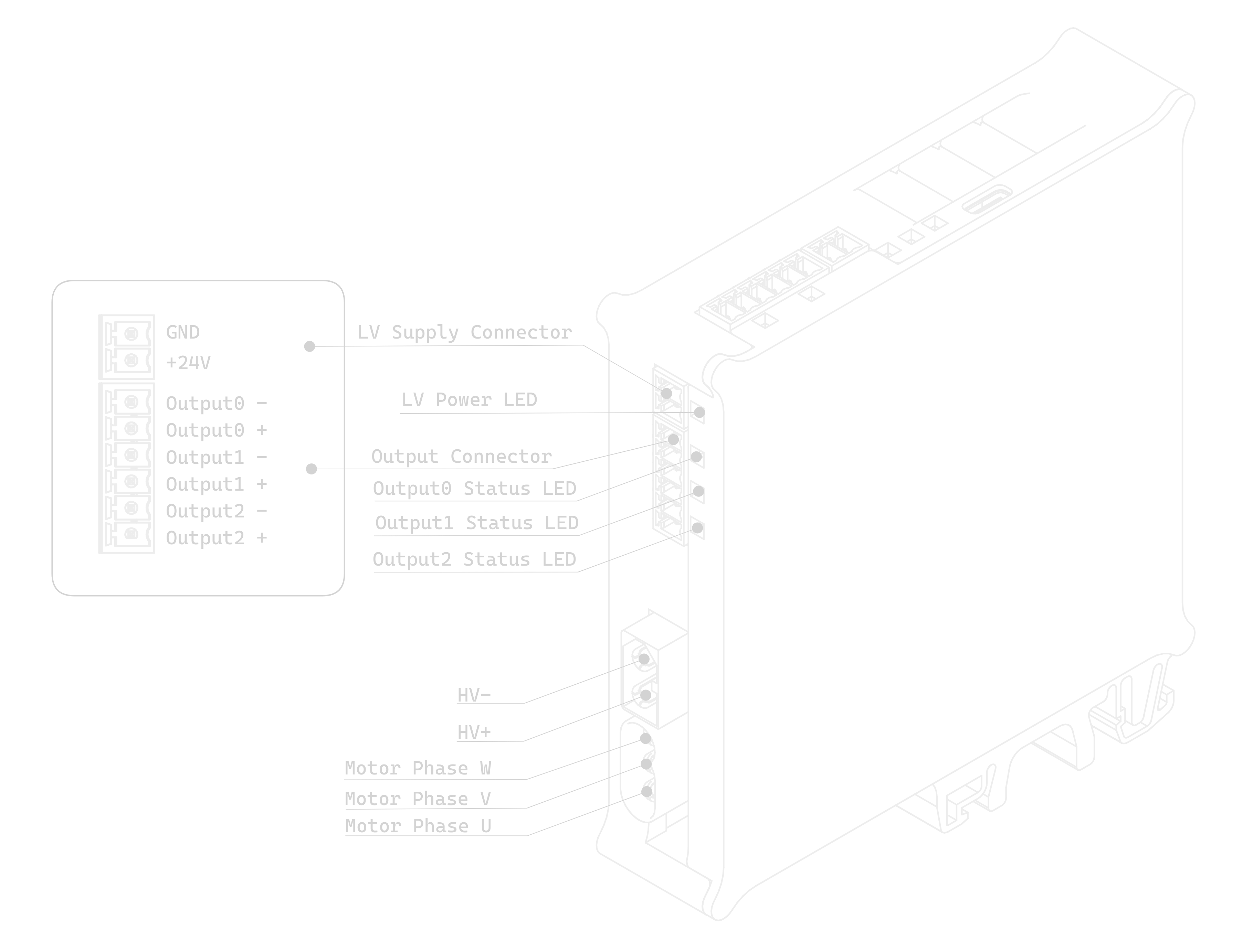
In addition to motor control and dual feedback, each STMBL drive has two +/-30V analogue inputs and three 24V / 2A digital outputs.
To use the STMBL, you will need to:
- connect your command, feedback, and motor to STMBL using suitable cables.
- Flash the firmware
- configure the drive for your motor using
Servoterm
- configure your Feedback interface
- find the correct Motor parameters for your motor
- configure your Command interface
Anatomy of the STMBL #
The STMBL consists of two separate PCBs that are made as one then assembled and split to be connected in the manner shown below. The vertical (top) board is the low-voltage (LV) board, and this handles the command, feedback, and configuration tasks. The STM32F405 microprocessor is in charge of these tasks.
The lower board is the high-voltage (HV) board, and this is where the power driver is situated. The only connection between the two boards is a serial connection through a 2.5kV isolation IC. To make this possible, there is a second STM32 chip on the lower board. This is an STM32F303 and is referred to as “F3” in the remainder of this document. The processor on the upper board is referred to as “F4”.
Logic power to the LV board should be 24V. A green LED will light adjacent to the socket when power is supplied.
The LV board is safe up to about 26V but take care that 0V is common with the PC GND before connecting a USB cable.
Motor power should be 30 to 350V, though the logic parts of the HV board may work at 24V for firmware flashing etc. Again, a green LED adjacent to the connector confirms that the board is powered-up.
The HV and LV boards are isolated in normal use but it is easy to accidentally connect them. One way to do this is via USB cables which can easily tie GND lines together through the setup PC.
It is imperative that the HV board should be powered from an isolated, low voltage supply when flashing firmware.
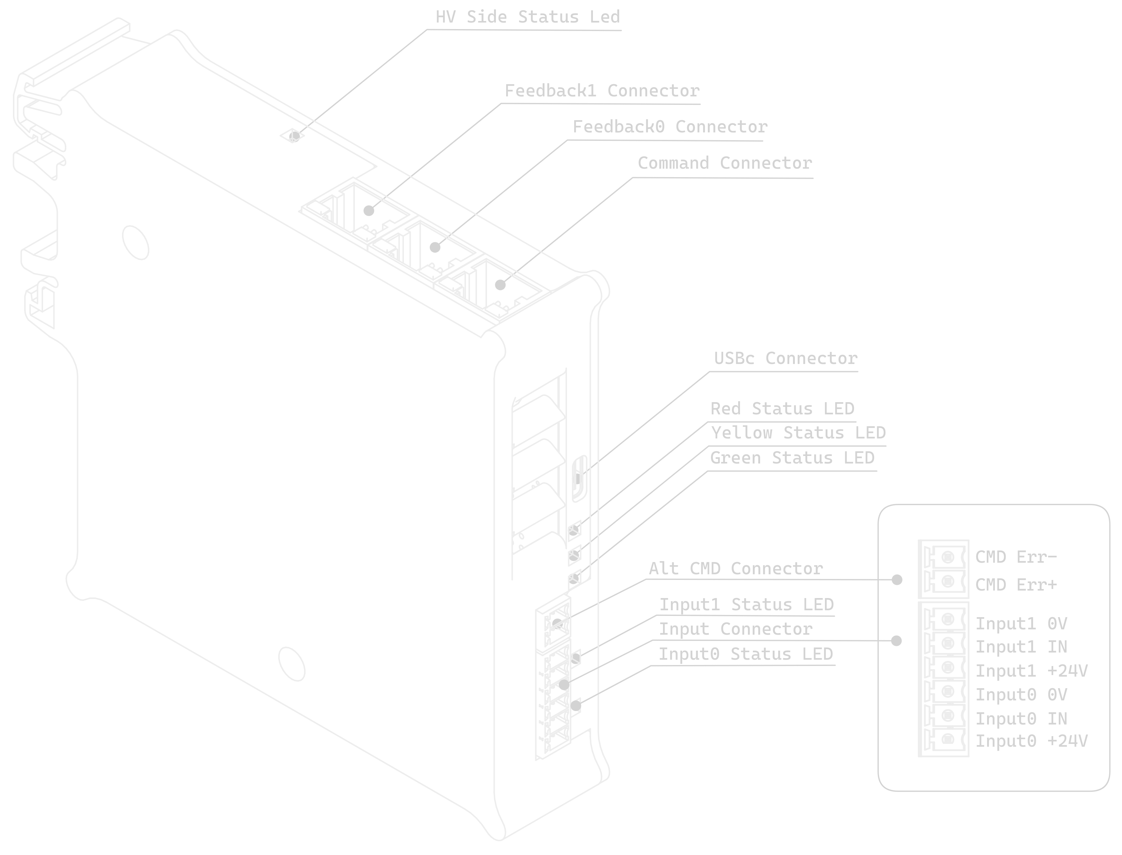
The command and feedback connectors use standard 8P8C (RJ45) connectors and standard CAT5 or CAT6 cables can be conveniently used. To connect to cables with larger conductors than supported by CAT5, it is possible to use, for example, Industrial CAT6a connectors which can accept core wires up to 1.6mm and overall cable diameters up to 9.0mm.
Feedback 0 will typically be the encoder or resolver mounted on the motor, and feedback 1 can be used to connect either Hall sensors for initial commutation or (potentially) scales mounted directly to the axes. See the Pinouts section of this document for pin assignments and typical wiring color codes.
The 6-way socket below the 24V logic power connector contains the three digital outputs. These are current-sinking (switch-to-GND) and each is adjacent to a 24V supply pin. DIO0 (nearest the top) is the one that is typically used to operate the holding brake on motors so-equipped.
On the top of the drive are two analog inputs, with 0V and 24V on either side to that an active sensors can be connected. These are typically used as variable-threshold digital inputs and are used, for example, for axis limit switches. However, it is relatively simple to configure them for other uses in the HAL.
Three LEDs on top of the unit indicate drive status. Red displays error codes (using Blink Codes). Amber indicates that all is well but the drive is not enabled, and green shows that the drive is active and operating normally. If no LEDs on the top of the board are illuminated, and the green power LEDs near the power connectors are illuminated, then it is probably necessary to flash the firmware. If there are LEDs lit on top of the drive, then it is probably safe to assume that firmware is loaded.
HAL (Hardware Abstraction Layer) #
STMBL uses a data flow graph to configure the drive for different types of motor, feedback, and operation mode. This is conceptually similar to the HAL in LinuxCNC, but the format and commands are different. Also, all pins are floating point so no data conversion is needed.
Here is the graphical representation of the default configuration for the LV board and for the HV board


An Application called Servoterm is used to interact with the HAL interface and configure the drive. You will need to install and launch this before it is possible to configure the STMBL.
STMBL HAL configuration does not use any commands other than the = sign and the Servoterm Commands.
Assuming that there is already a motor connected to the drive and that the drive is powered up, the Servoterm display should already be indicating the motor position feedback. Rotating the motor shaft by hand might produce something like:
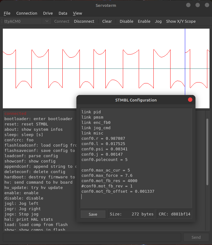
Though it equally well might not if the configuration is set up for a resolver and the motor has an encoder. It should be possible to make the motor turn at this point without any further configuration. The commands that follow will set the hv0 module up to simply rotate the motor open-loop in direct-mode (like a stepper motor) with an excitation current of 0.5A. This should be safe for most motors that the STMBL is a good match for, but you should choose your own value. For an explanation of direct and quadrature current, see the section on Motor Basics.
hv0.pos = sim0.vel
hv0.d_cmd = 0.5
hv0.en = 1
The rotation speed can be altered by changing the sim0 frequency:
sim0.freq = 5
STMBL HAL contains a number of components that have built-in linking behavior.
Resolvers #
Resolver phase - Setting the phase is very important to get resolver output. ‘res0.phase = X’ sets the phase. The number is between 0 and 1. Set for the highest output.
Resolver speed - In motor drives, resolver speed is typically 1. One rotation of the resolver equals one rotation of the motor. You will want to add these settings to the config so that the drive powers up with the settings as default.
Motor pole count / setting motor feedback offset #
Motor pole count in data sheets is often a total pole count rather than STMBL required ‘pole pair’ count. This is easy to see when running the com_test: type ’link com_test’. This should start the motor turning slowly in open loop, while displaying on the graph. Ideally, the green and black lines will match closely. If they are not the same speed (same number of peaks), then the motor poles setting is wrong. ‘conf0.polecount’ can be set without stopping the test. Set it till the number of green and black peaks are the same. Now the peaks may be offset on the graph. ‘conf0.motor_fb_offset’ will set this. Adjust this number till the black and green lines match. You’ll want to add these settings to the config so the drive starts with these defaults.
Jogging test #
If you set the jogging checkbox at the top of ServoTerm and then enable the drive with: ‘fault0.en = 1’, using the left and right cursor keys on the keyboard can be used to jog the motor. The escape key will disable the drive quickly if something is not quite right. If there is a fault, then you will need to toggle the enable pin to 0 and back to 1 again. If the drive oscillates, try adjusting the ‘conf0.j’ setting for inertia.
Drive the motor with a sine wave #
- Connect it
rev0.in = sim0.msin - Set amplitude
sim0.amp = 1(in rad) - Set frequency
sim0.freq = 0.5(in Hz) - Enable
fault0.en = 1
Or constant velocity #
- Connect it
rev0.in = sim0.vel - Set frequency
sim0.freq = 0.5(in Hz) - Enable
fault0.en = 1
Pressing Esc at any time will disable the drive. To reenable, press reset or type fault0.en = 0 followed by fault0.en = 1.
Components/templates/config list and examples #
You can find the list of components, template and configs in the Hal components, templates and configs section.
Flashing Firmware #
Requirements to build firmware #
The GCC cross-compiler for Arm: gcc-arm-none-eabi-gcc https://launchpad.net/gcc-arm-embedded/+download You will also need the STMBL source code, available from https://github.com/freakontrol/stmbl. You can either clone this as a git archive or just download a current snapshot as a zip file. In order for the STMBL Makefiles to be able to find the gcc binaries, you may need to create the file toolchain-user.mak to point to the correct folder and version number.
Requirements to flash firmware #
The STM32 chips have a built-in ROM bootloader, this means that it should be impossible to “brick” the boards. Each of the two CPUs in the STMBL drive needs both a dedicated bootloader to start the STMBL firmware and the firmware itself.
Linux/Unix #
To flash the boards with USB, you will need the dfu-utils package http://dfu-util.sourceforge.net. To flash the boards with a stlink programmer over SWD, you will need the stlink package https://github.com/texane/stlink
Windows #
You will need the STM Virtual Comport driver to connect with Servoterm http://www.st.com/content/st_com/en/products/development-tools/software-development-tools/stm32-software-development-tools/stm32-utilities/stsw-stm32102.html And the DfuSe USB device firmware upgrade STMicroelectronics extension to flash the firmware over USB https://www.st.com/en/development-tools/stsw-stm32080.html
Checking for Existing Firmware - F4 board #
Before flashing firmware, it is worth trying to figure out if your board is completely blank or has been pre-flashed with a bootloader or firmware. If the board will connect with Servoterm, then it already has a firmware and STMBL bootloader. “about” will show the firmware information of the F4 board. “hv about” will give the same information about the F3 board. Go to the Updating Firmware section to flash new firmware. If the board lights any LEDs other than the green power-good ones near to the power input connectors, then there is likely to already be a firmware installed. Go to the Updating Firmware section if you need to update the firmware. If the board is powered with 24V to the LV board and connected with USB to a PC, then it will report as “STMBL Virtual ComPort:” in the Apple System Profiler, “ID 0483:5740 STMicroelectronics STM32F407” in lsusb in Linux, and “STMBL Virtual COM Port” in the Windows device manager if there is a full firmware + STM32 bootloader installed. If the board shows “STM32 BOOTLOADER” (Mac), “0483:df11 STMicroelectronics STM Device in DFU Mode” (Linus lsusb), or “STM32 BOOTLOADER” (Windows Device Manager) when powered up (without using the boot pads), then this indicates that it already has an STMBL bootloader. (though no harm is done by re-flashing this) If the LV board does not show up at all on the USB bus, then attempt to put it in ROM boot mode by shorting the boot pads together while connecting the 24V. You should see “STM32 Bootlader” (Mac), “STMicroelectronics STM Device in DFU Mode” (Linux lsusb), or “STM32 BOOTLOADER” (Windows Device Manager) In this case, you will need to flash both the STMBL bootloader and the STMBL firmware. Go to the Flashing the LV board with no bootloader section.
Checking for existing firmware - F3 board #
With 24V to the F3 board and with the F4 board unpowered, look at the red LED under the fan, near the USB connector. If the HV board has both an STMBL bootloader and an STMBL Firmware installed, then it will illuminate only the green power LED and will flash the red LED slowly to indicate no comms with the F4 board (which is why this check should be done with the F4 board unpowered). Go to the Updating Firmware section in this scenario. If the F3 board does not flash the red LED when the F4 is unpowered, then there is no bootloader and no firmware flashed. Go to the Flashing the HV board with no bootloader section. If the F3 board has only a bootloader flashed and no or broken firmware, then the red LED will flash rapidly. Use the instructions in Updating Firmware in this case. The boards can also be flashed with a SWD programmer, but that process is not documented here. It can be convenient to flash the boards to test them before separating the halves and before installing the IRAM module and bus capacitors if you have a self-built or part-assembled board. Precompiled Binary versions of the firmware can be downloaded from https://github.com/freakontrol/stmbl/releases When compiling from the source code, firmware flashing is handled by specifying a makefile target for each of the firmware sections.
Updating Firmware #
The firmware on both the F3 and F4 board can be updated through the F4 USB port and without access to the boot pads. Connect 24V to both the F3 and F4 boards. In the source software folder, type git pull to get the latest software version. Type make clean to ensure that all files are freshened. Type make followed by make binall to create the binary files to be flashed. Type make btburn to program the F4 firmware and transfer a copy of the F3 software or type make all_btburn to program the F4 firmware + bootloader and transfer a copy of the F3 software
this will overwrite your config
There should then be a quantity of text output culminating with a progress bar like:
Downloading to address = 0x08000000, size = 2756
Download [=========================] 100% 2756 bytes
You can now re-connect with Servoterm and check the firmware version with about. Updating the F3 firmware is done via Servoterm using the hv_update command. This should give output similar to:
hv_update: SEND_TO_BOOTLOADER
hv_update: ERASE_FLASH
hv_update: SEND_APP
hv_update: status: 4%
...
hv_update: status: 95%
hv_update: CRC_CHECK
hv_update: status: 100%
hv_update: FLASH_SUCCESS
hv_update: status: 100%
hv_update: SLAVE_IN_APP
If this fails multiple times, go to the Flashing the HV board with no bootloader section.
Flashing the LV board with no bootloader #
To flash the initial bootloader and firmware, it is necessary to put the STM32 CPU into ROM bootloader mode. You do this by shorting together the two pads marked “boot” on the LV board while connecting the 24V supply. This is a bit of a fiddle but should only need to be done once when the board is first built. For the exact location of these pads, see the illustration in the
Anatomy of the STMBL section. Typically, a small screwdriver can be used for this purpose. At this point, the board should appear as an “STM32 Bootloader” in the USB tree of the attached PC. Follow the
Updating Firmware instructions and use the make all_btburn command.
Flashing the HV board with no bootloader #
Connect the USB cable to the HV board and short the boot pads on the HV board while connecting 24V to the HV input. To put it into bootloader mode. Again, it should appear in the USB device tree. Follow the
Updating Firmware instructions but use the make f3_all_btburn command.
linuxcnc #
STMBL supports Mesa Smartserial to communicate with LinuxCNC. http://linuxcnc.org/docs/html/man/man9/sserial.9.html
https://www.youtube.com/watch?v=5CKMrOy0ZXk
STMBL config #
At the end of your STMBL config, load sserial:
link sserial
Set the scale:
linrev0.scale = 5
Example: HAL config for Position mode with Position feedback #
This is an example for one axis, Mesa 5i25 and one STMBL board, added to a .hal file in a machine config:
# This is an example for linuxcnc hal in position mode for the x-axis:
net xposcmd joint.0.motor-pos-cmd => hm2_5i25.0.stbl.0.0.pos_cmd
net xvelcmd joint.0.vel-cmd => hm2_5i25.0.stbl.0.0.vel_cmd
net xposfb joint.0.motor-pos-fb <= hm2_5i25.0.stbl.0.0.pos_fb
net xenable joint.0.amp-enable-out => hm2_5i25.0.stbl.0.0.enable
net xfault joint.0.amp-fault-in <= hm2_5i25.0.stbl.0.0.fault
net xindex joint.0.index-enable <=> hm2_5i25.0.stbl.0.0.index_enable
Example: Full Machine Config with STMBL boards, Mesa 7i80, Mesa 7i77, Analog Outputs, Encoder Inputs #
See https://github.com/aShure/cnc-configs/tree/master/justinbieber